E Core Transformer Design
Transformer Basics Working Principle Construction Types Applications
How To Make A Transformer Bright Hub Engineering
Simple Circuits And Projects Ei Core Transformer Design Calculator
Magnetics 1 Copyright C By John Wiley Sons 03 Design Of Magnetic Components A Inductor Transformer Design Relationships B Magnetic Cores And Materials Ppt Download

Nicore Characteristics And Advantages Of E Core

Evaluation Of An Efficient Transformer Core Design Semantic Scholar
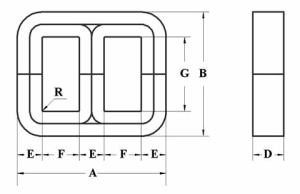
Every A L value corresponds to 2 slightly different gaps, depending on whether the mating part is another E core or a plate (P).
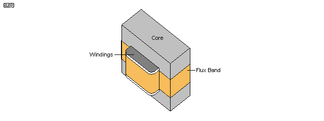
E core transformer design. The first one with a unity turn ratio and second one with a turn ratio of one thousand. Signal booster and graduated in to making transformers for Cellular Industries, UPS, Invertors and Custom Design CVT's, Ultra Isolation Transformers. E-shaped core are more symmetric solutions to form a closed magnetic system.
The excitation current is defined as the magnetizing current needed to energize the core. Wire type, size, and number of turns. Selection of transformer core.
Transformers ship same day. Magnetic Material (Tape) C Core Construction Mandrel Magnetic Material (Tape) Toroidal Core Construction " Mandrel Figure 3-14. Get contact details & address of companies manufacturing and supplying EI Lamination Core, EI Transformer Laminations, E & I Lamination across India.
They typically consist of the following components:. Each one of these materials. A core has a different type of A L (Ungapped core inductance Coefficient) depending on the core material, core size, and core type.
Temperature rise for the transformer when it is used in a specified temperature environment. The Article Library brings you the latest technology news and trends, product information, supplier updates, and design how-tos. The designer first needs several known factors to design a transformer.
Transformer Design with Magnetics Ferrite Cores. ATX power supplies up to about 800-1000W or so. For example, if we need to have larger amount of current in our design, which means that the required Kg from the cores would shoot up.
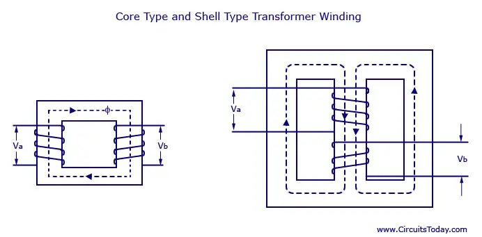
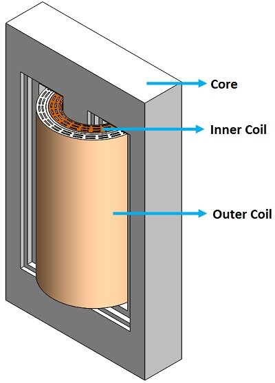
Basically a transformer will have the following main components:. The cross-section area of the core type transformer is rectangular, whereas the cross-section area of the shell type transformer is square, cruciform two slipped, or three stepped in shapes. The basic step to building a transformer is to create the model of the object.
The core losses are categorized in to three components h ysteresis losses , f lux l eakage and e ddy c urrents. The model will give you a blueprint of the conceptual results, way before you start investing money and resources in the actual construction of the transformer. Mold Design (Core And Cavity Extraction ) In creo 3.0 PART 1 - Duration:.
The winding window area should be as wide as possible to maximize winding breadth and minimize the number of layers. Using the equation shown below,. Selecting appropriate copper winding parameters:.
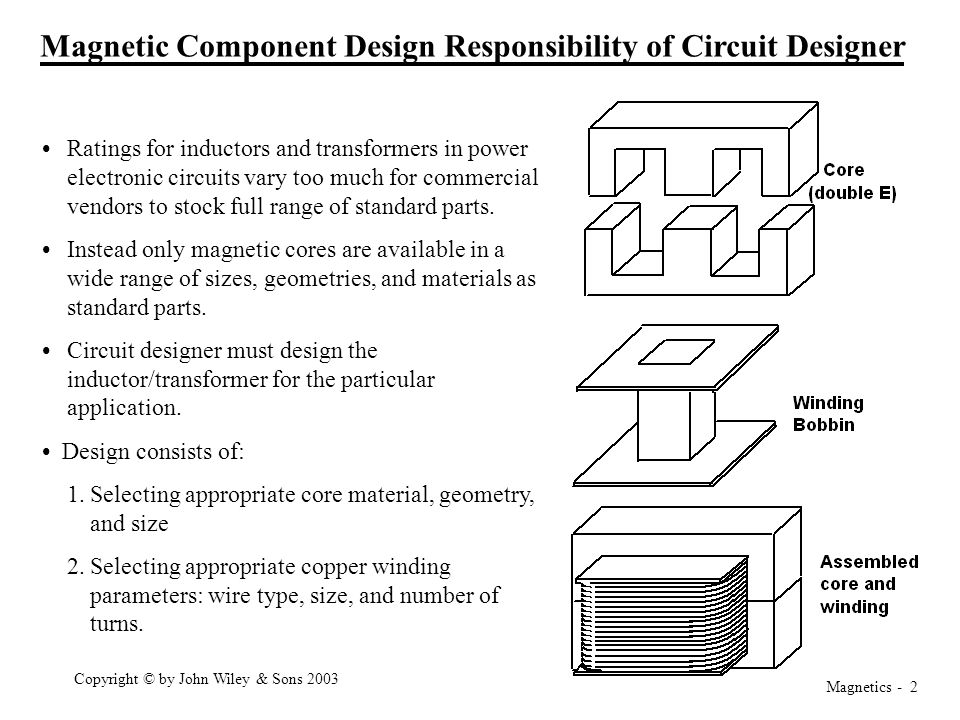
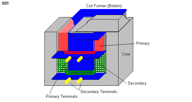
Core (double E) Winding Bobbin Assembled core and winding. This means that the core will be closer to saturation. In the core type transformer construction, one half of each winding is wrapped around each leg (or limb) of the transformers magnetic circuit as shown above.
Transformers have many different uses, but their basic design and operation remains the same. Transformers – Power Transformers are in stock at DigiKey. E-E cores in the ETD or EC series, the relative pro-portions are quite similar for all core sizes.
The core shape and window configuration are important for high-frequency transformer design to minimize losses. Combining this with the equation above enables the window area, A W, from the core. Basic Constraints Core loss Typical value of for ferrite materials:.
Engineering drawing will be automatically produced. The power handling capacity of a transformer core can also be determined by its WaAc product, where Wa is the available core window area, and Ac is the effective core cross-sectional area. Design of core Rectangular core:.
Transformers used for the distribution and control of electrical energy consist of a primary and secondary copper wound coil carrying a magnetizing current surrounding an iron core which is used for the transferring of power from the primary to the secondary coil. Transformer design3 15.1 Transformer Design:. • Circuit designer must design the inductor/transformer for the particular application.
At Mech-Tronics, we design and manufacture transformers and inductors in various shapes and materials depending on the specifications and requirements of your application. Selecting appropriate core material, geometry, and size 2. Order before 8pm EST Standard Shipping (Mon – Fri.
Depending on circuit designs, core types and applications of transformers, there are different …. Magnetic Builder is a useful magnetic design software. Popular type of core material are N67, N87, N27, N26, PC47, PC95, etc.
Transformer Cores, Planar E, E22/6/16/R, 3F3, E22/6/16/R, 26.1 mm, 78.5 mm² + Check Stock & Lead Times 1,164 in stock for same day shipping:. This relation can be used to estimate the temperature rise of the transformer as a function of flux density in the core. EFD and EPC cores are used when a low profile is required.
Magnetics Powder Core products - Kool Mu ® (sendust), MPP (molypermalloy), Kool Mµ ® MAX, Kool Mu ® Hƒ, Edge TM, High Flux, XFlux ®, and 75-Series materials - are distributed air gap cores that are primarily used in power inductor applications, specifically in switched-mode power supply (SMPS) output filters, also known as DC inductors. The design optimizes the ratio of core volume to winding and surface area. It offers low eddy current losses.
The core is assembled of a continuous strip or ribbon of transformer steel wound in the form of a circular or elliptical cylinder. If you intend to have DC current in the transformer, you should apply the same design constraints as when designing a inductor intended for DC. Ae Effective Cross Section Area:.
2.2 Fundamentals for broadband transformers in the range 10 kHz to over 1 GHz – an example Broadband transformers are constructed primarily using closed core shapes, i.e. The model includes the effect of a nonlinear B-H curve in the core and shows how to connect the transformer model to the external circuits using Electric Circuit interface. Inductor design18 14.3 Multiple-winding magnetics design using the Kg method The Kg design method can be extended to multiple-winding magnetic elements such as transformers and coupled inductors.
The transformer core design is the most important thing in an SMPS transformer construction. Power transformer design. In 3-phase transformer cores, the legs are of equal size, and all three legs are wound.
𝟎𝟒 cm5 Step # 4:. Top Click here to try Online Magnetics Builder (design tool) now. All E cores in power materials can be gapped, preferably in a standard range of A L values.
Assembly is simple using printed circuit bobbins and one piece clamps. • Design consists of:. The core of single phase core type transformer is a single window core.
Fundamentals of Power Electronics Chapter 15:. It underuses transformer core, magnetizing it in just 1 polarity, but on other hand it gets favorable MOSFETs voltage and current tradeoffs, pretty much like full bridge, being cheaper solution. Such construction allows the core flux to follow the grain of the iron.
Transformer design part 1 SINGLE PHASE CORE TYPE TRANSFORMER. Cold-rolled steel of high silicon content enables the designer to use considerably higher operating flux densities with a lower loss per kg. If the transformer is designed to be at the edge of saturation without DC current, it will saturate.
Transformer Cores, E, E65, 3C90, 147 mm, 540 mm² + Check Stock & Lead Times. The EE cores are constructed in the same way as C cores, but they have an additional overwind, as shown in Figure 3-18. Due to the small core losses (in comparison with a laminated core), the temperature rise will drop drastically when the output power is reduced.
This is the first of my series of semi advanced electronics design videos focusing on practical design and application. Similar to using an "E" and "I" together, a pair of "E" cores will accommodate a larger coil former and can produce a larger inductor or transformer. Also, the manufacturer of ferrite cores provides.
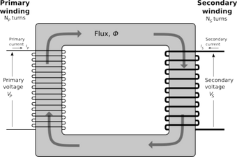
In core, type windings surround a part of the core whereas in shell type core surrounds windings. E core transformer design products are most popular in Domestic Market, Southeast Asia, and North America. The simulation is performed for two different cases;.
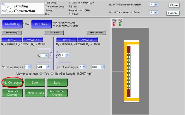
What is magnetic builder (Inductor and Transformer design tool)?. Chokes and wideband transformers. C-I Core A Low Cost Solution to a New Generation in Transformer Design.
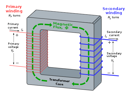
A ferromagnetic core, called E-, I-, U-, L-, toroidal, pot, or planar cores, depending on their shape Primary and secondary coils, also known as windings. Most of the time, the electric circuit is wound around the center leg, whose section area is twice that of each individual outer leg. The magnetic flux flows through two closed magnetic paths which decrease the core losses and hence increase the efficiency of transformer.So, shell type transformer gives more output compared to similar core type transformer.
There are two main types of transformers which can be categorized by the shape of the magnetic core. So we can now determine the number of turns in the primary. Now, we take all these constraints, and we can design the rest of the transformer.
If an air gap is required, the centre leg of the "E" is shortened so that the air gap sits in the middle of the coil to minimise fringing and reduce electromagnetic interference. You should consult with a core manufacturer to obtain the specific characteristics and power-handling capabilities for each type and. That means, the core Kg must be larger than the design Kg.
The MID-MHC series includes universal input offline transformers with one to three outputs of 3.3 to 24V to demonstrate the capabilities of the package. Calculation of electrical condition Electrical conditions, 𝐾𝑒 = 0.145𝐾𝑓 2 𝑓2 𝐵 𝑚 2 × 10−4 = 0.145 × 4.44 × 502 × 1.62 × 10−4 = 1. Step # 3:. Such a design tends to exhibit more losses, but is very economical to manufacture.
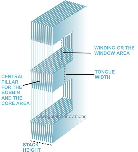
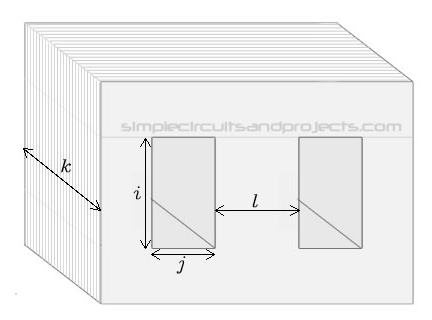
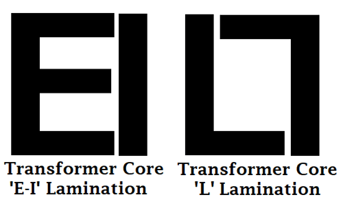
One common design of laminated core is made from interleaved stacks of E-shaped steel sheets capped with I-shaped pieces, leading to its name of 'E-I transformer'. Magnetic materials used to design low and high frequency transformers are shown in Table 7-1. As a result, power output, inductance and winding area are maximized with a minimal core weight, volume and PCB footprint.
Common ferrite core types are toroidal, closed-core, shell and cylindrical. In shell type transformer width of central limb is 2 to 3 times the depth of core. The core losses are generated in the steel core of the transformer by the excitation current.
This minimizes AC winding resistance. Calculation of core geometry Core geometry, 𝐾𝑔 = 𝑃𝑡 2𝐾 𝑒 𝛼 = 513.16 2×1.×5 = 𝟏𝟖. E of the ferrite core used.
The video is on inductor design theor. One of the main benefits we get using shell-type is that the core gives a good support against the electromagnetic forces that can occur between the current carrying. The assembled three-phase transformer is shown in Figure 3-19.
2.6 or 2.7 B is the peak value of the ac component of B(t), i.e., the peak ac flux density So increasing B causes core loss to increase rapidly This is the first constraint P fe = K fe. For a transformer using a sine or square wave, one needs to know the incoming line voltage, the operating frequency, the secondary voltage(s), the secondary current(s), the permissible temperature rise, the target efficiency, the physical size one can use, and the cost limitations. A ferrite transformer has a magnetic core in which coil (inductor) windings are made on a ferrite core component.
The first step is to determine the type of core for the design. If you have unique needs, Würth Elektronik will design custom flyback transformers based on the MID-MHC package for you. Fundamentals of Power Electronics Chapter 14:.
In this transformer design, we used E-I core type. The mating part is a plate or an ungapped E core. Find here EI Lamination Core, EI Transformer Laminations manufacturers, suppliers & exporters in India.
As you search for the right component for your project, you need to consider:. These are core type transformers, and shell-type transformers (and less commonly, air core transformers).We shall discuss here the core type transformer. In core type transformer the lamination is cut in the form of L-shape whereas, in shell type transformer, the laminations are cut in the E and L shapes.
Back Automation and Control. One of the basic steps in transformer design is the selection of proper core material. It is a tool for user to create his/her own magnetic component (inductor and transformer) by selecting different ferrite core, bobbin type and winding method.
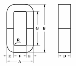
Effective Magnetic Path Length:. Toroids and double-aperture cores. Core loss is ignored), or.
It is normally used for high-frequency applications. It is used for core type distribution transformer and small power transformer for moderate and low voltages and shell type transformers. Divided core designs such as P/RM cores or small E/ER cores, which allow.
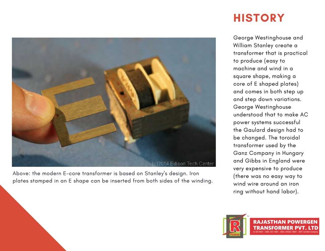
You can ensure product safety by selecting from certified suppliers, including 18 with ISO9001, 2 with ISO, and 1 with OHSAS certification. Iron core stampings (configured either as U/T or E/I, generally the later is used more extensively) Central plastic or ceramic bobbin surrounded by the above iron core stampings. Default is asymmetric gap (A) ;.
Pot Core, E-Core And Toroidal Transformers Discover Our Products And Capabilities. In core type transformer the ratio of depth to width of core varies between 1.4 to 2. A similar relation has now been found for planar E transformers.
For Use With-Core Material Grade:. This means there are two limbs as shown in the figure below. While there are many transformer design programs out there, we have out together a list of the top six solutions we believe are the best for transformer design.
This empirical formula is valid for wire wound transformers with core shapes like RM and ETD. This improves noise performance relative to E-core designs. Transformers rated for class E (1°C), class F (150°C) and class H (180°C) are also available.
Thus for all cores in the ETD or EC series, the usable surface area, A S, is approximately 22 times the winding win-dow area, A W. E I Transformers, E I core Transformers, E I Type Transformers , manufacturer E I Transformers Transformers We are manufacturing transformers for various equipments like computer monitors, T.V. So it fairly usual to see 2-switch forward in e.g.
In both types of transformer core design, the magnetic flux linking the primary and secondary windings travels entirely within the core with no loss of magnetic flux through air. We chose E-I core as the winding is much easier when compared to toroidal, but efficiency is very high (95%-96%). This method is applicable when – Copper loss dominates the total loss (i.e.

Power Design Inductor Transformer

Transformer Construction And Transformer Core Design

Custom Ei Core Transformer Design Power Manufacturers For Factory Buildings Ecko
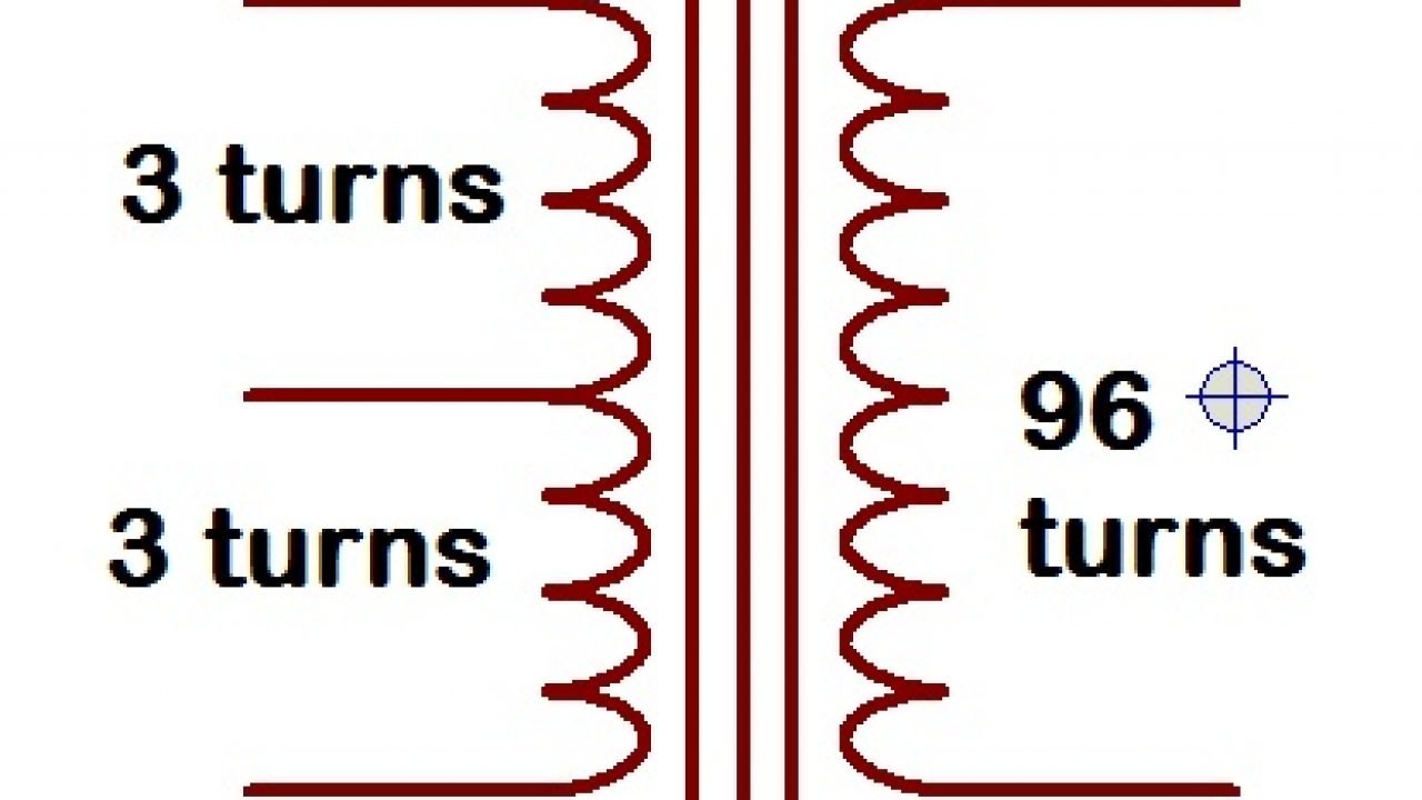
Ferrite Transformer Turns Calculation With Example

Transformer Core Types Youtube
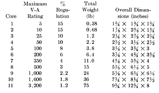
Electronic Transformers Design Chart
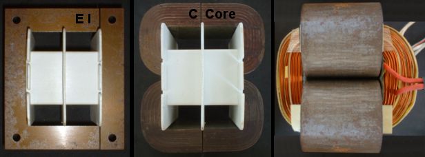
Valve Amps Output Transformers

How To Build Step Down Transformers With Calculations

Transformer Construction And Transformer Core Design
Transformer Wikipedia
Transformers Part 2 Beginners Guide To Electronics

Transformers Part 1 Beginners Guide To Electronics
Q Tbn 3aand9gcth7g5okrznzecwryc4 Nekfaqe8ldrhmqafo15fcvskfe1oenx Usqp Cau
Grain Oriented Silicon Steel And Iron Nickel C Core And E Core Cut Cores Tlm Composants

How A Toroidal Core Transformer And Choke Works Amgis

Low Cost C I Core Magnetic Metals

Output Equations And Main Dimensions Design Of Transformers

Transformer Wikipedia

Transformer Construction And Transformer Core Design
2
Transformer Calculation Software Electronic Circuits
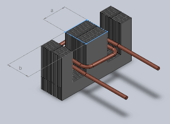
Calculating Mains Frequency Power Transformers
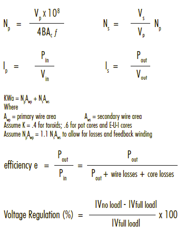
Magnetics Transformer Design With Magnetics Ferrite Cores

Calculations For Design Parameters Of Transformer Engineer Experiences

E Core Transformer Design Stlfinder
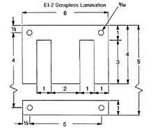
Electronics Transformer Design Wikibooks Open Books For An Open World
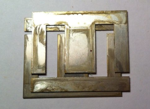
Calculating Mains Frequency Power Transformers

Pdf Design And Modeling Of Multi Winding Transformers Interfacing Inverters And Mains
Single Phase Transformer

Pdf Core Lamination Selection For Distribution Transformers Based On Sensitivity Analysis

Ei Shib M6 Orient Core Power Transformers Available Now Sw1x Audio Design

Chapter 3 Design Of Transformers 3 1
China Custom Design Silicon Steel Ei Core For Small Transformers China Silicon Steel Sheet Transformer Core

Transformer Construction And Transformer Core Design
Different Types Of Transformers And Their Applications

Electronics Transformer Design Wikibooks Open Books For An Open World
Magnetics Builder Design Magnetic Inductor And Transformer Tool Software

Transformer Design Formulas Transformer Physics Mathematics
Rajasthan Powergen Transformer Pvt Ltd The Modern E Core Transformer Is Based On Williamstanley S Design Rajasthanpowergen Elecrama Elecramaexhibition Elecramaparticipate Distributiontransformer Powertransformer Electricity
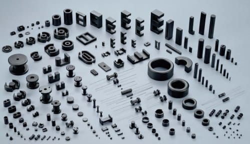
How To Design Ferrite Transformers Of Various Topologies

Electronics Transformer Design Wikibooks Open Books For An Open World

Design Of Magnetic Components W5jgv Pages 1 48 Text Version Fliphtml5

Transformer Construction And Transformer Core Design

Transformer Construction And Transformer Core Design

Figure 3 From Analytic Design Method For Integrated Transformers Of Resonant Converters Using Extended Fundamental Frequency Analysis Semantic Scholar

Transformer Design

Donwload Transformer Calculator Program For Calculating Number Of Coils And Wire Thickne Toroidal Transformer Electrical Transformers Electronic Circuit Design
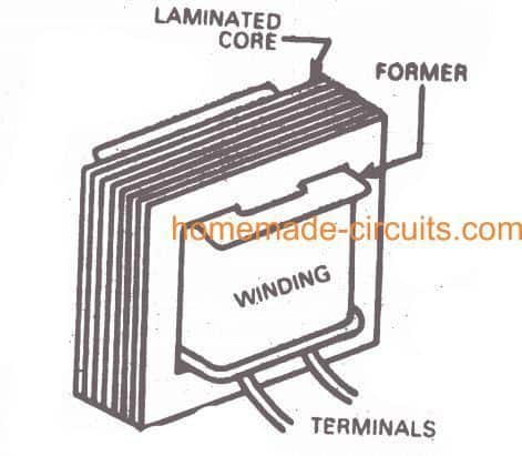
How To Build Step Down Transformers With Calculations

Figure 4 From High Frequency Power Transformers With Foil Windings Maximum Interleaving And Optimal Design Semantic Scholar

How To Design Your Own Transformer For Smps Power Supply Circuits

Electronics Transformer Design Wikibooks Open Books For An Open World
Http Ece Colorado Edu Ecen5797 Course Material Ch15handouts Pdf

Transformers Part 2 Beginners Guide To Electronics
1
Apps Dtic Mil Dtic Tr Fulltext U2 A Pdf

Pdf Core Loss And Excitation Current Model For Wound Core Distribution Transformers
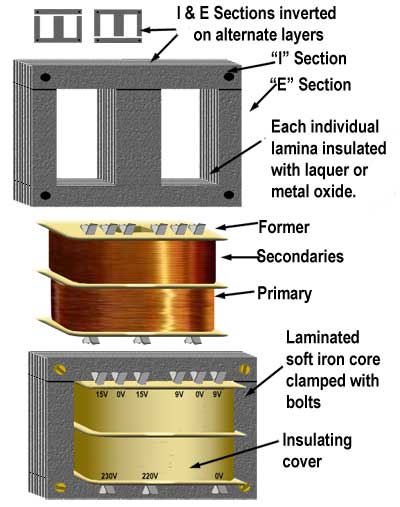
Power Transformers

How To Design Your Own Transformer For Smps Power Supply Circuits
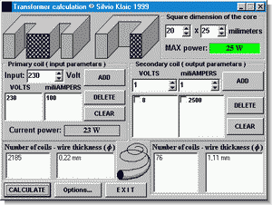
Transformer Calculator Program Electronics Projects Circuits
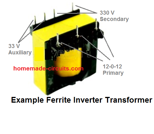
How To Calculate Ferrite Core Transformers Homemade Circuit Projects

Pdf Design Modeling And Analysis Of A Compact Planar Transformer
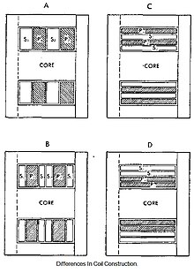
Electronics Transformer Design Wikibooks Open Books For An Open World

Transformer Wikipedia

Magnetics Plexim
Q Tbn 3aand9gcrh Aco2wo5ifdraqd5cdhic2t7val3vofyfik07c7vrpq9pzxw Usqp Cau

China Ee Ei Ef Type Core Smps Transformer With Customized Design China Custom Transformer Ee Transformer
Www Infineon Com Dgdl An 1024 Pdf Fileid 5546dae0f6d

How To Indentify The Core Number E I Yt 74 Youtube

History Of Transformers
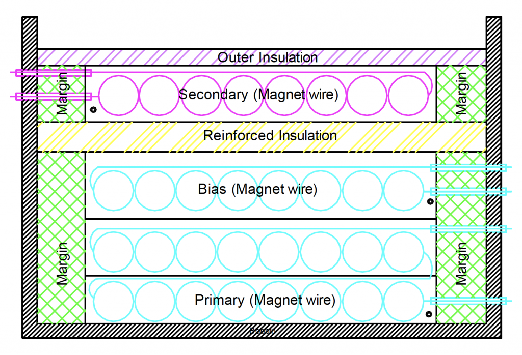
12 Steps For Designing Smps Transformers The Talema Group

Output Equations And Main Dimensions Design Of Transformers
Www Infineon Com Dgdl An 1024 Pdf Fileid 5546dae0f6d
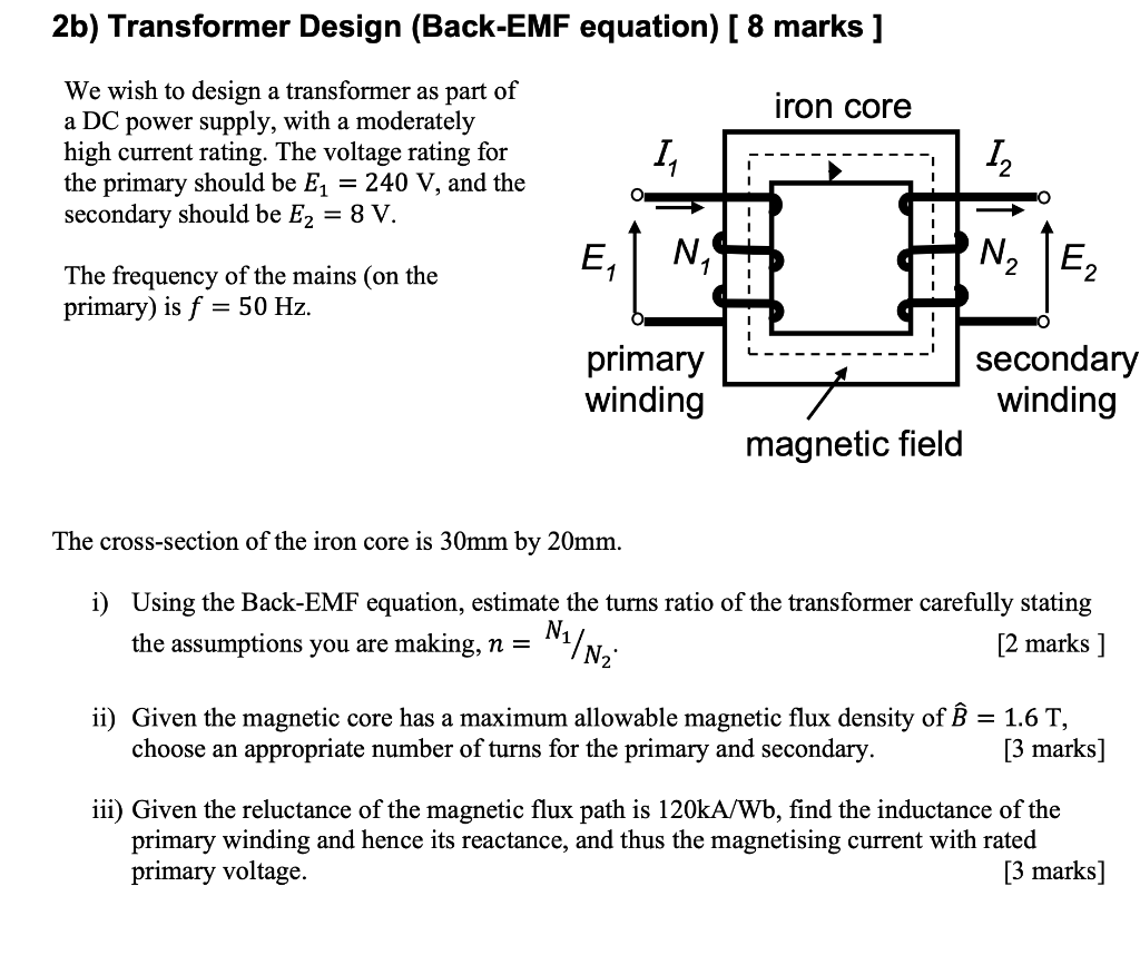
Solved 2b Transformer Design Back Emf Equation 8 Mar Chegg Com

Pdf An Amorphous Core Transformer Design And Experimental Performance Benedito Luciano Academia Edu
Grain Oriented Silicon Steel And Iron Nickel C Core And E Core Cut Cores Tlm Composants

A Cool Kilowatt Plate Transformer
How To Design Your Own Transformer For Smps Power Supply Circuits
Help For The High Frequency Transformer Design

Magnetic Core Wikipedia

Low Cost C I Core Magnetic Metals
R Core Transformer James Transformer Custom Toroidal Transformer R Core Transformer O Core Transformer C Core Transformer Ei Transformer

Geometries Loop And Break

7 Xfmrdsgn 3 1 Transformer Power Supply

Power Transformers Basics Transformers Design Electronics Basics Transformers
Transformer Engineering Fandom
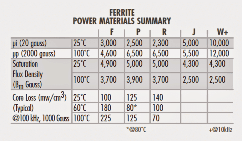
Ferrite Core Material Selection Guide For Smps Homemade Circuit Projects

Transformer Basics Diy Audio Heaven
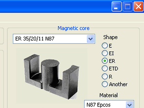
Advanced Smps Transformer Design Program Electronics Projects Circuits
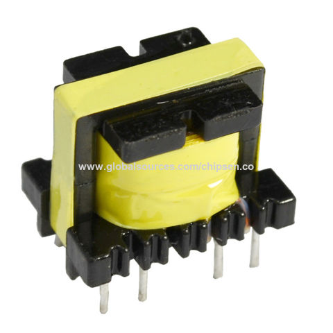
China Odm Oem Ei19 Ei24 50 60h Ei Core Transformer For Audio Video System Pcb Design On Global Sources
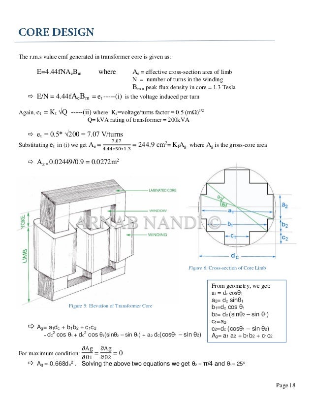
Tranformer Design

J K Audio Design Ei Core Versus C Core Transformer
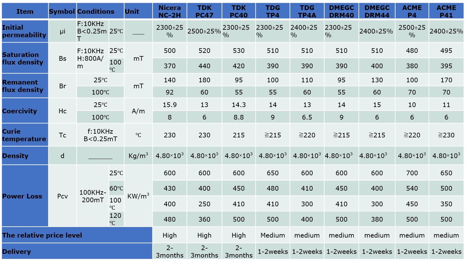
Transformer Guide Zettler Magnetics Europe
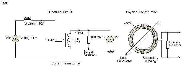
Transformers Part 2 Beginners Guide To Electronics

Power Transformer Design

Transformer Construction And Transformer Core Design
Q Tbn 3aand9gcrtch9tgcfbrhxeuyzknfebr 5dk5yrg2yp9jx9ep S5qdevno7 Usqp Cau

How To Build Step Down Transformers With Calculations

Transformer Types Wikipedia


